TL;DR
The Honeywell Home S8610U is a universal intermittent pilot module designed to replace a wide range of older ignition controls on gas furnaces, boilers, and water heaters. If your pilot won't light, your igniter sparks but nothing ignites, or your system locks out after three tries, a failed intermittent pilot module is a common cause — and the S8610U is one of the most installer-friendly universal replacements on the market. (Note: always rule out a clogged pilot orifice, dirty flame sensor, or failing gas valve before replacing the module.) Read on for everything you need to know before you buy.
Replacing a faulty intermittent pilot module doesn't have to mean a week without heat or an expensive service call — if you choose the right replacement ignition control. The Honeywell Home S8610U has become the go-to universal ignition control for HVAC technicians and serious DIYers alike, thanks to its broad compatibility, field-adjustable timing, and proven reliability. In this guide we cover every spec, installation consideration, and common question so you can buy with confidence.
Our Top Pick: Honeywell Home S8610U Universal Intermittent Pilot Module
The S8610U earns its reputation as the industry's most versatile intermittent pilot replacement. Field-selectable timing, wide OEM compatibility, and a robust lockout-with-manual-reset circuit make it the single part most HVAC pros stock on every service van. Score: 9.4 / 10
Honeywell Home S8610U — Complete Overview
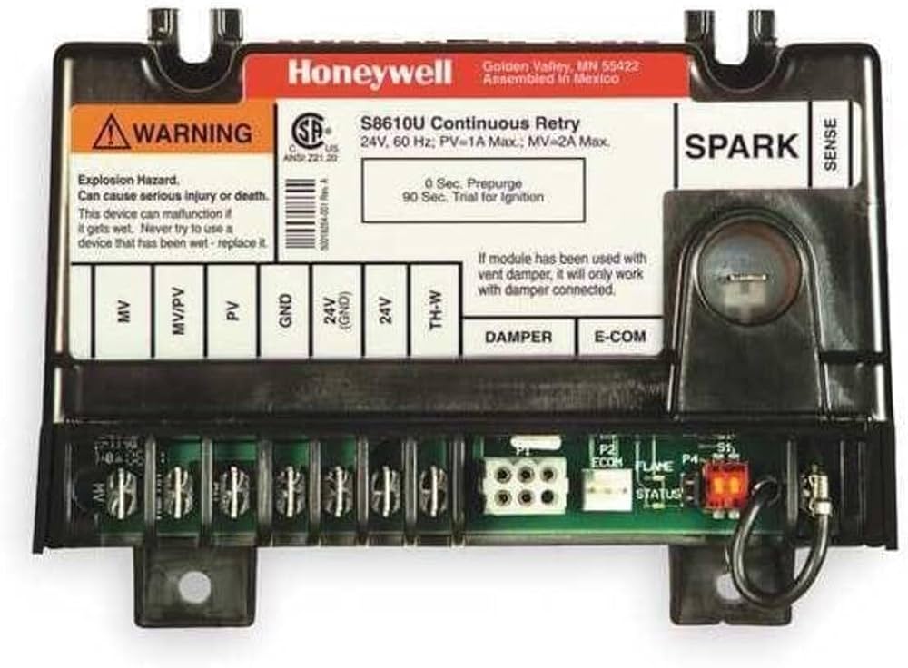
The S8610U is a direct-spark intermittent pilot (IP) ignition module that controls the entire ignition sequence for intermittent-pilot gas appliances. (It is not used on standing-pilot systems, which keep a continuous pilot flame and use a thermocouple or thermopile rather than an electronic ignition module.) When the thermostat calls for heat, the module energizes the igniter electrode, opens the pilot gas valve, confirms a pilot flame via the flame sensor rod, then opens the main gas valve. If it doesn't detect flame within the trial-for-ignition (TFI) period, it de-energizes everything and either retries or locks out — depending on how its internal DIP switches are set.
What sets the S8610U apart from single-application replacement modules is its "universal" designation. Honeywell engineered it with field-selectable timing options that let a single part number stand in for dozens of OEM-specific modules from Honeywell's own legacy catalog as well as compatible units from Robertshaw, White-Rodgers, and other manufacturers. This dramatically reduces parts-room inventory and virtually eliminates the "wrong module ordered" scenario that can strand a homeowner for days.
The module operates on 24 VAC (transformer power supplied by the appliance's control board) and communicates with standard thermostat terminals: W (call for heat), C (common), and the dedicated pilot valve, main valve, and igniter outputs. Its flame-sensing circuit uses rectified DC current detection — the same technology used across virtually all modern gas appliance controls — meaning it works with any standard flame-sensing rod without recalibration.
Physically, the S8610U mounts on a standard 1-5/8 inch, 4-hole snap-in base (also called a "Molex" style in the HVAC trade) and ships with the most common wiring harness adapters. The enclosure is UL listed and rated for temperatures from −40 °F to +175 °F, making it appropriate for both indoor and draft-exposed equipment rooms.
Pros
- Universal compatibility covers dozens of legacy module part numbers
- Field-selectable DIP switches for TFI timing (10, 15, or 90 seconds) and retry/lockout behavior
- Manual reset lockout with clear LED diagnostic indication
- UL listed; meets ANSI Z21.20 safety standard
- Snap-in base for tool-free mounting in most appliances
- Handles both 24 VAC pilot valve and main gas valve independently
- Works with standard flame-sensing rods — no special electrode required
- Widely stocked at HVAC supply houses for same-day pickup
Cons
- Not compatible with direct-spark ignition (DSI) or hot-surface ignition (HSI) systems
- DIP switch settings must be correctly matched to the original module — incorrect settings can affect warranty or appliance timing
- Requires basic wiring knowledge; not appropriate for absolute first-timers without guidance
- Some appliances with proprietary wiring harnesses need an additional adapter pigtail
- Price has risen in recent years; budget buyers sometimes balk at the cost vs. off-brand alternatives
This site earns a commission from purchases made through links on this page. Our editorial opinions remain independent.
Detailed Specifications
Part Number
S8610U3009 (most common retail SKU)
Control Type
Intermittent Pilot (IP) Ignition Module
Supply Voltage
24 VAC, 50/60 Hz
Current Draw
Max 0.5 A (excluding igniter and valve loads)
Trial for Ignition (TFI)
Field-selectable: 10 sec, 15 sec, or 90 sec
Ignition Retries
Field-selectable: 3 retries then lockout, or continuous retry
Lockout Reset
Manual (requires thermostat cycle or power interruption)
Flame Sensing
Rectified DC flame current, min 0.5 µA
Pilot Valve Output
24 VAC, max 1.0 A
Main Valve Output
24 VAC, max 1.0 A
Igniter Output
High-voltage spark, ~15 kV open circuit
Operating Temperature
−40 °F to +175 °F (−40 °C to +79 °C)
Mounting Base
Snap-in, 1-5/8 in. 4-hole Molex pattern
Certifications
UL listed, ANSI Z21.20 compliant
Dimensions (approx.)
4.0 in. × 2.8 in. × 1.6 in.
Weight
Approx. 0.4 lbs
Understanding the DIP Switch Settings
The S8610U ships with four DIP switches that configure its ignition timing and retry behavior. Getting these right is the single most important step in the installation. Setting them incorrectly won't necessarily damage anything, but it can cause nuisance lockouts (TFI too short), safety timing violations (TFI too long for the appliance's listed specification), or continuous retry loops that stress the gas valve.
⚠ Important: Match DIP Settings to Your Original Module
Always cross-reference the S8610U cross-reference chart (included in the box and available from Honeywell's technical documentation) for your specific original module part number. Do not guess at TFI timing. If you no longer have the original module's documentation, look up the appliance model number to find the OEM-specified ignition timing.
| Switch | Function | Position OFF | Position ON |
|---|---|---|---|
| SW1 | Trial for Ignition (TFI) — Part 1 | See combined table below | See combined table below |
| SW2 | Trial for Ignition (TFI) — Part 2 | See combined table below | See combined table below |
| SW3 | Retry / Lockout | 3 retries then lockout | Continuous retry (no lockout) |
| SW4 | Inter-purge Timing | 15 sec inter-purge | 5 sec inter-purge |
SW1 + SW2 Combined TFI Settings
| SW1 | SW2 | Trial for Ignition Period | Common Application |
|---|---|---|---|
| OFF | OFF | 10 seconds | Most residential furnaces (default / most common) |
| ON | OFF | 15 seconds | Older boilers, some commercial units |
| OFF | ON | 90 seconds | Long pilot tube runs, some boilers |
| ON | ON | Not used / Reserved | — |
💡 Pro Tip: 10-Second TFI is the Default for Most Homes
The vast majority of residential gas furnaces manufactured after 1985 use a 10-second TFI. If your original module is an S8610A, S8610B, or S8610C, the S8610U with SW1 and SW2 both OFF will match the original timing perfectly.
Compatibility: What Does the S8610U Replace?
Honeywell designed the S8610U as a catch-all replacement for its own legacy IP modules and for many compatible third-party units. The included cross-reference guide lists over 40 direct replacements. Below are the most commonly encountered obsolete part numbers the S8610U replaces.
| Original Module | Brand | Notes |
|---|---|---|
| S8600A, S8600B, S8600C, S8600H, S8600M | Honeywell | Early IP modules; confirm base type |
| S8610A, S8610B, S8610C, S8610E, S8610F | Honeywell | Direct predecessors; most common cross |
| S8670A, S8670D | Honeywell | Combination modules; check wiring |
| Q3400A Igniter/Sensor used with older modules | Honeywell | S8610U controls same electrode |
| 780-845, 780-846 Series | Robertshaw | Verify 24 VAC supply voltage |
| 50E47, 50E48 Series | White-Rodgers | May require adapter harness |
| LCI-2 Series | ITT General Controls | Older commercial boiler modules |
⚠ Not Compatible With These Systems
The S8610U cannot replace direct-spark ignition (DSI) modules, hot-surface ignition (HSI) modules, or any electronic ignition system that does not use a standing pilot burner with a separate pilot valve and flame-sensing rod. If your appliance ignites the main burner directly without a pilot flame, you need a different control entirely.
Installation Guide
Installing the S8610U is within reach of a capable DIYer, but the work involves gas appliances and 24 VAC wiring. If you are not comfortable with basic wiring tasks, or if your jurisdiction requires a licensed technician for gas appliance repair, hire a professional. The steps below are a general guide — always follow the specific installation instructions included with your S8610U.
⚠ Safety First
Before beginning: shut off the gas supply at the appliance shutoff valve, set the thermostat to its lowest setting, and disconnect power to the appliance at the circuit breaker or by unplugging it. Verify with a non-contact voltage tester that power is off before touching any wiring.
Step 1 — Document the Existing Wiring
Photograph the existing module from multiple angles before disconnecting anything. Note which wire color goes to which terminal: PV (pilot valve), MV (main valve), MV/PV (combination valve common), GND (ground), IGN (igniter), SENSE (flame sensor), and the 24 VAC thermostat terminals. Label wires with masking tape if needed.
Step 2 — Remove the Old Module
Disconnect all wiring from the old module terminals. Release the module from its snap-in base by pressing the two retaining tabs simultaneously and lifting up. If the base itself is damaged, the S8610U ships with a replacement snap-in base.
Step 3 — Set the DIP Switches
Before mounting the new module, configure SW1–SW4 according to the cross-reference chart for your original module number. Refer to the DIP switch table in this guide. Setting the switches after mounting is possible but more difficult.
Step 4 — Mount the S8610U
Align the module with the existing snap-in base (or the replacement base if you installed one) and press firmly until both retaining tabs click into place. The module should have no lateral play once seated.
Step 5 — Reconnect Wiring
Connect each wire to its corresponding terminal on the S8610U using your photos and labels as reference. The S8610U uses the same terminal designations as Honeywell legacy modules. Tug each connector gently to confirm it is seated. If your wiring harness plug does not physically mate with the S8610U terminals, use the included adapter pigtail.
Step 6 — Restore Power and Gas
Restore circuit breaker power, then slowly open the gas shutoff valve. Set the thermostat above room temperature to trigger a call for heat. Watch through the observation window (if present) or listen for the igniter clicking, the pilot lighting, and then the main burner lighting. The entire sequence should complete within the TFI period you selected.
Step 7 — Verify the Flame Signal
An experienced technician will use a microamp meter in series with the flame sensor wire to verify the flame current is above the 0.5 µA minimum threshold (ideally 1.5–4 µA for a healthy flame). DIYers who do not have a µA meter should at minimum confirm the system completes three consecutive heating cycles without lockout. If lockout continues, the most likely cause is a dirty flame sensor rod — clean it gently with fine steel wool, reconnect, and retest before assuming the module is defective.
💡 Tip: Lockout LED is Your Diagnostic Friend
The S8610U's onboard LED flashes a code when it locks out. A steady LED after a failed cycle typically means no flame was detected. Before condemning the new module, check the pilot orifice for blockage, verify the gas valve is open, and inspect the flame sensor rod for corrosion or carbon buildup — these are far more common causes of ignition failure than a faulty module.
Troubleshooting Common Issues
| Symptom | Likely Cause | What to Check |
|---|---|---|
| No spark from igniter | No 24 VAC to module; bad igniter wire; cracked electrode | Check transformer output; inspect high-voltage wire for cracks; inspect electrode tip |
| Spark present, pilot does not light | Pilot orifice clogged; gas valve not openi |
