TL;DR
The White-Rodgers 50A55-843 is a universal integrated furnace control board designed to replace a wide range of OEM boards in gas furnaces. Whether your furnace is throwing fault codes, failing to ignite, or cycling erratically, this guide walks you through everything you need to know before purchasing — compatibility checks, installation tips, key features, and what to watch out for.

- Best for: PSC blower motor furnaces from Carrier, Bryant, Payne, Lennox, Heil, Tempstar, and similar brands with HSI or intermittent pilot ignition.
- Biggest gotcha: Not compatible with ECM variable-speed blower motors without an adapter module.
- Verify first: Original OEM board part number, igniter voltage (80V vs 120V), and blower motor type before purchasing.
- Skip it if: Your furnace is under warranty or uses a communicating thermostat (Infinity/Evolution).
A failing furnace control board can turn a cold night into a genuine emergency, and finding the right replacement quickly is critical. The White-Rodgers 50A55-843 has become one of the most widely recommended universal furnace control boards on the market, trusted by HVAC technicians and savvy DIYers alike for its broad compatibility and reliable diagnostics. Before you purchase, read this complete buying guide so you know exactly what you're getting — and whether it's the right fit for your system.
Safety Notice
Furnace control board replacement involves working with high-voltage electrical components and gas systems. Always shut off power at the breaker and close the gas supply valve before beginning any work. If you are not confident in your abilities, hire a licensed HVAC technician. Improper installation can result in fire, carbon monoxide poisoning, or equipment damage.
Top Pick: White-Rodgers 50A55-843 Universal Furnace Control Board
The 50A55-843 earns its reputation as the go-to universal replacement board for gas furnaces — broad OEM cross-reference coverage, built-in diagnostic LED codes, and field-adjustable timing settings make it the most practical and cost-effective choice for replacing a failed integrated furnace control.
What Is the White-Rodgers 50A55-843?
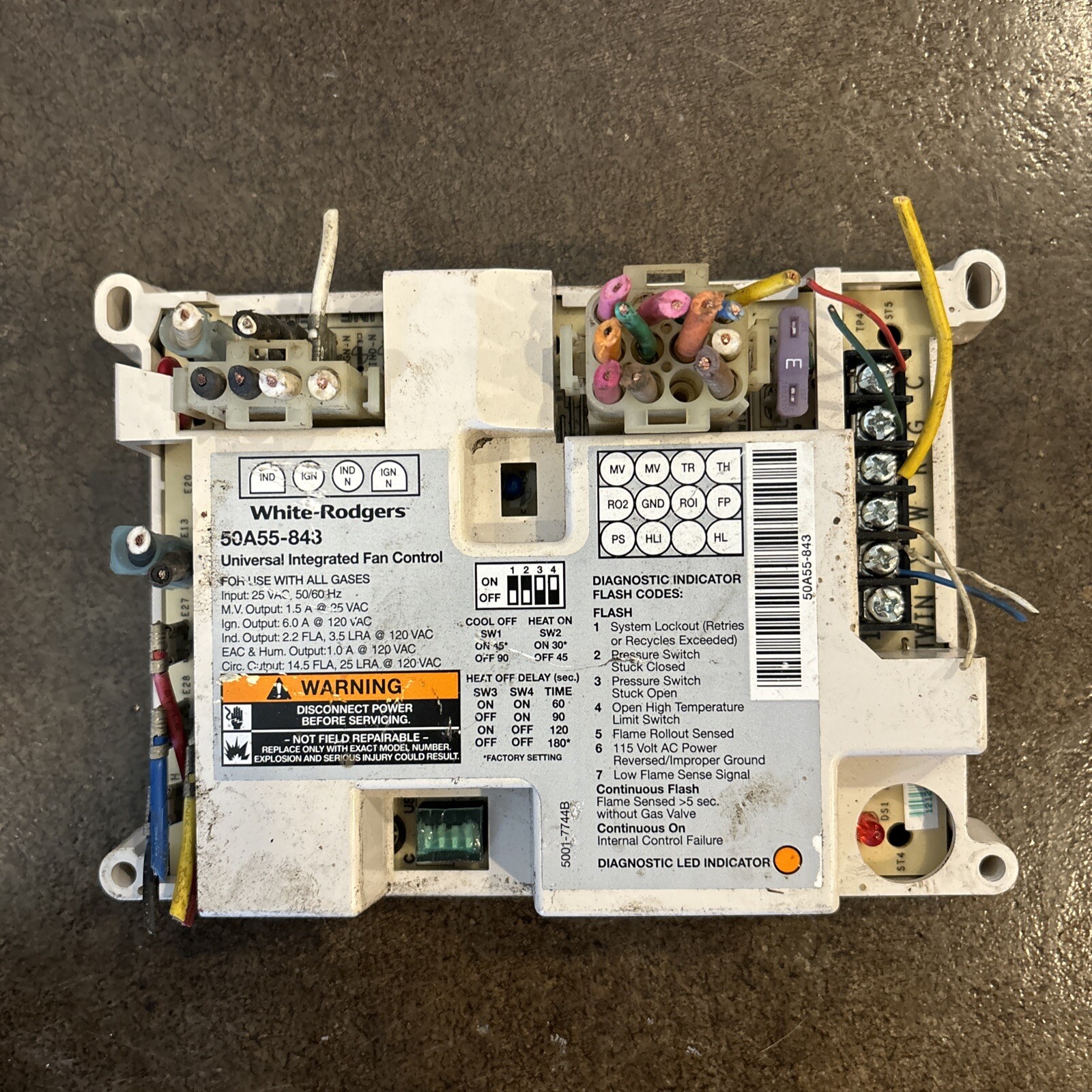
The White-Rodgers 50A55-843 is an integrated furnace control (IFC) board manufactured by Emerson Electric under the White-Rodgers brand — one of the most trusted names in HVAC controls. It is designed as a universal replacement for a broad range of OEM-specific integrated furnace control boards used in residential and light commercial gas forced-air furnaces. The board manages ignition sequencing, inducer motor control, blower motor timing, safety circuit monitoring, and diagnostic fault reporting all in a single unit.
Unlike a dedicated OEM board that is engineered for one specific furnace model, the 50A55-843 uses a series of DIP switches and jumper configurations to match the operational parameters of dozens of different furnace models and brands. This flexibility is what makes it a staple in HVAC service vans — technicians can carry one board and cover a large percentage of service calls rather than stocking dozens of model-specific replacements.
The board is built around a proven microprocessor platform that has been refined over multiple product generations. It supports both hot surface ignition (HSI) and intermittent pilot ignition systems, handles single-stage and multi-stage gas valve configurations, and works with standard 24V thermostat control wiring. The diagnostic LED system uses blink codes that can be cross-referenced to a fault table printed directly on the board's label, making troubleshooting faster and more accessible.
It's worth noting that "50A55-843" refers to a specific part number in a broader family of White-Rodgers 50A55-series boards. Always verify the exact part number you need, as closely related variants like the 50A55-289, 50A55-474, or 50A55-571 may have different configurations, igniter voltage ratings, or blower timing parameters. This guide focuses specifically on the -843 variant.
Manufacturer
White-Rodgers (Emerson Electric)
Part Number
50A55-843
Board Type
Integrated Furnace Control (IFC)
Ignition Compatibility
Hot Surface Ignition (HSI), Intermittent Pilot
Supply Voltage
120V AC, 60 Hz
Control Voltage
24V AC (thermostat circuit)
Gas Valve Support
Single-stage and two-stage configurations
Blower Timing
Field-adjustable via DIP switches
Diagnostics
LED blink codes with on-board fault chart
Replaces
Multiple OEM boards across major brands
Compatibility: Does the 50A55-843 Fit Your Furnace?
Compatibility is the single most important factor to verify before purchasing the 50A55-843. The board is classified as universal, but "universal" in the HVAC world does not mean it works with every furnace ever made — it means it is engineered to replace a defined list of OEM part numbers across multiple brands. The cross-reference list for this board typically includes OEM boards from brands such as Carrier, Bryant, Payne, Lennox, Heil, Tempstar, Comfortmaker, Arcoaire, Keeprite, and others, depending on the revision level of the 50A55-843 you purchase.
The correct procedure is to locate the original board's part number — usually printed on a label affixed to the board itself — and then check it against the 50A55-843 cross-reference list provided by White-Rodgers/Emerson. This cross-reference list is typically included in the product packaging and is also available through HVAC parts distributors. Do not rely solely on the furnace model number for compatibility; two furnaces of the same model may have received different control boards at different production dates.
Key technical compatibility checks include: the igniter voltage (80V or 120V for hot surface igniters — using the wrong voltage will burn out an 80V igniter almost immediately), gas valve wiring connector configuration, inducer motor interface, and blower motor speed taps. The 50A55-843 is designed to work with PSC (permanent split capacitor) blower motors using multi-speed taps — it is not compatible with ECM (electronically commutated motor) variable-speed blower motors without additional hardware, which is a common point of confusion.
ECM Motor Warning
If your furnace uses a variable-speed ECM blower motor, the 50A55-843 is NOT a direct compatible replacement without the correct ECM module adapter. Installing this board with an ECM motor without the proper interface will result in blower motor failure or the motor not operating at all. Confirm your blower motor type before purchasing.
Also verify the number of ignition trials and lockout parameters match your application. Some furnaces — particularly those installed in specific code jurisdictions or applications — require specific lockout timing that must be achievable through the DIP switch configurations on the 50A55-843. The board's installation manual details all available DIP switch settings; review these against your furnace's original wiring diagram before finalizing your purchase decision.
Compatibility Tip
Take a clear photograph of your existing control board (both sides), the board's part number label, and the furnace's wiring diagram before removing anything. This documentation will be invaluable during the cross-reference check and the re-installation process.
Pre-Purchase Verification Checklist
- ☐ Located and recorded the OEM part number from the existing board's label
- ☐ Confirmed the OEM part number appears on the 50A55-843 cross-reference list
- ☐ Verified blower motor type is PSC (not ECM variable-speed)
- ☐ Identified hot surface igniter voltage rating (80V or 120V)
- ☐ Confirmed ignition type (HSI or intermittent pilot) matches board capability
- ☐ Checked furnace warranty status (replacement may void coverage)
- ☐ Photographed existing wiring and furnace wiring diagram
Key Features and Technical Highlights
The 50A55-843 packs a comprehensive set of features into a single integrated board, replacing what used to require multiple separate control components in older furnace designs. Understanding these features helps you evaluate whether the board suits your specific application and gives you a framework for troubleshooting if issues arise post-installation.
Integrated Diagnostic LED System
One of the most practically useful features of the 50A55-843 is its on-board LED fault code system. A single bi-color LED (or in some revisions, dual LEDs) flashes blink sequences that correspond to specific fault conditions. A chart on the board's label — visible through the furnace's observation port or door — decodes these sequences into readable fault descriptions. Common fault codes cover issues like pressure switch faults, limit switch trips, flame sensor failures, ignition lockouts, and rollout switch trips. This system dramatically reduces diagnostic time compared to older boards that provided no fault information.
Adjustable Blower Timing via DIP Switches
The board includes a bank of DIP switches that allow field adjustment of several critical timing parameters without any additional programming tools. Adjustable parameters typically include heat blower on delay (the time between burner ignition and blower activation), heat blower off delay (the time the blower continues running after the burner shuts off to extract residual heat), and cooling blower operation settings. These adjustments allow the board to replicate the behavior of the original OEM board it is replacing, which is essential for maintaining proper heat exchanger temperatures and preventing nuisance limit trips.
Comprehensive Safety Circuit Monitoring
The 50A55-843 continuously monitors a full set of safety inputs including the high-limit switch, rollout switch, pressure switch (draft inducer proving), and flame sensor signal. If any of these inputs fall outside acceptable parameters, the board responds with an appropriate action — whether that's immediate lockout, a retry sequence, or a hold condition — and logs the fault via the LED diagnostic system. This multi-layer safety architecture is what allows a universal board to be trusted in life-safety gas appliance applications.
Hot Surface Ignition Control with Retry Logic
The board's ignition control section manages the hot surface igniter warm-up period, gas valve opening timing, flame verification window, and retry-on-failure logic. In the event of a failed ignition attempt, the board will typically retry a configured number of times before entering a lockout state. The retry and lockout parameters are critical for both safety and comfort — too few retries can cause nuisance lockouts on marginal ignition systems, while too many retries with a failed igniter can cause gas accumulation. The 50A55-843's factory defaults and DIP-switch-adjustable options are designed to cover the majority of residential furnace applications.
Note on Revision Levels
The 50A55-843 has been manufactured in multiple revision levels over its production run. Minor differences in connector layouts, DIP switch functions, or cross-reference lists may exist between revisions. Always read the installation documentation included with the specific unit you receive, rather than relying solely on documentation found online, which may correspond to a different revision.
Pros and Cons of the White-Rodgers 50A55-843
Pros
- Broad cross-reference compatibility replaces dozens of OEM boards
- Built-in LED diagnostic fault codes speed up troubleshooting
- Field-adjustable DIP switch timing settings for flexible configuration
- Trusted White-Rodgers/Emerson brand with long HVAC industry track record
- Supports both hot surface ignition and intermittent pilot systems
- On-board fault chart visible through furnace observation window
- Widely available through HVAC distributors and online parts suppliers
- Typically less expensive than sourcing a hard-to-find OEM board
- Comprehensive installation manual with wiring diagrams included
- Single-stage and two-stage gas valve support
Cons
- Not compatible with ECM variable-speed blower motors without adapter
- Requires careful DIP switch configuration — incorrect settings can cause issues
- Cross-reference list does not cover all furnace models universally
- Igniter voltage must be verified before installation (80V vs. 120V)
- Multiple revision levels can cause documentation confusion
- Some OEM connector pinouts differ and require wiring adaptation
- Not a plug-and-play solution for those unfamiliar with HVAC wiring
- May not replicate all advanced features of high-end OEM boards
See current price on the White-Rodgers 50A55-843
This site may earn a commission on purchases made through links on this page at no additional cost to you. Our recommendations are based on technical merit and suitability for the application, not commission rates.
Installation Overview: What to Expect
Installing the 50A55-843 is a moderately complex task that is within reach of a capable DIYer with electrical experience, but it is not a beginner project. The process involves safely de-energizing the furnace, documenting existing wiring, removing the old board, configuring the new board's DIP switches, transferring wiring connections, and systematically testing the system before restoring normal operation. Plan for two to four hours if this is your first control board replacement.
Step 1: Document Everything Before You Touch Anything
Photograph the existing board from multiple angles, capturing every wire connector, its position on the board, and the wire colors or labels. Locate and photograph the furnace's wiring diagram (usually affixed to the inside of the furnace cabinet door or panel). If the original board's wiring diagram is different from the 50A55-843's layout, you will need to cross-reference terminal functions — not just connector positions. This documentation phase is where most successful DIY installations are won or lost.
Step 2: Configure DIP Switches Before Installation
Before mounting the new board, set the DIP switches to match your furnace's original operating parameters. The installation manual will map specific switch positions to blower on/off delays, ignition retry counts, and other parameters. Cross-reference these against your original furnace's installation manual or OEM board documentation. It is much easier to configure the switches with the board in hand than after it's mounted in the furnace cabinet.
Step 3: Transfer Connections Systematically
With power off and confirmed off with a non-contact voltage tester, transfer one connector at a time from the old board to the new board, checking off each connection against your documentation as you go. Pay particular attention to the line voltage (120V) connections, the thermostat (2